
Spin-Offs From the Suction Sail
The suction sail is an innovative design that uses a small amount of energy to redirect a large flow of crosswind to assist ship propulsion, reducing the amount of thrust required from ship propellers. Spin-offs from the suction sail concept can be applied to other maritime transportation applications.
Introduction
The concept of the suction sail begins with conventional boat sails that converts the kinetic energy of crosswinds to vessel propulsion, applying Newton’s law of motion that there is a kinetic reaction for every kinetic action. Designers of early sails, kite makers and builders of early airplane wings focused on the interaction between wind on the upwind side of the sail, not the shadow side. The early aviation sector discovered the important role of the upper shadow side of a wing sustaining ‘lift’ as compared to the wing underside.
Developers of yachts experimented with adapting an aeronautical wing or airfoil sail to vessel propulsion, by redirecting crosswind kinetic energy. Airfoil construction and ‘angle-of-attack’ in relation to crosswind direction made greater use of the shadow side of the airfoil to provide propulsive force, as long as air flowed over the shadow side as water flows down the side of a tilted mug of water. Airfoil design produced a low-pressure zone near the forward edge, diverting a large amount of crosswind rearward around the airfoil shadow side to produce greater propulsive force.
Suction Sail
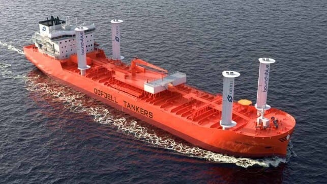
The suction sail is a deck-mounted airfoil with an extractor fan installed at the upper end, to pull air in through slits in the airfoil to develop a low-pressure zone across the airfoil shadow side. That modification greatly increases the amount of crosswind that is diverted rearward around the shadow side of the airfoil, greatly increasing propulsive force by several orders of magnitude. The concept has potential to be adapted to other areas of maritime propulsion, including below the waterline involving hydrofoils and even Flettner Rotors.
Suction Hydrofoils
The ability of suction sail technology to greatly increase the equivalent of ‘lift’ along the shadow side of an airfoil-sail provides the basis to adapt the concept to operate underwater, in the form of suction hydrofoils. When operating submerged, a small propeller would pull a small volume flow rate of water through narrow slit-type inlets built into the hydrofoil upper surface. Water would flow through the interior of the hydrofoil and out through an outlet installed below the hydrofoil or at its far end, potentially increasing the low-speed ‘lift’ of the hydrofoil.
Using suction technology to increase ‘lift’ along the top surface of a hydrofoil increases potential to raise a vessel hull above water at lower sailing speed, also increasing the amount of weight that a vessel could carry on its hydrofoils. Raising the vessel hull at lower speed reduces drag when sailing through severely choppy water, allowing the vessel to sail at low-speed over extended distances with hull above water. While most hydrofoil vessels are designed to sail at speed, there might actually be a market for low-speed hydrofoil vessels capable of sailing smoothly through choppy water.
Suction Rotor
The success of suction sail technology during real world operation provides a basis to combine it with a competing technology, the vertical-axis spinning cylindrical Flettner Rotor. A hollow rotor with inlet slits and an extraction fan installed at its upper end offers the concept of a suction rotor. Reversible blades would allow the rotor and extraction fan to spin in either clockwise of counter-clockwise directions while pulling air through the rotor. A planetary overdrive gear would spin the extractor fan at extreme rotational speeds, sustaining a low-pressure zone inside the cylinder while diverting air inward through the inlets.
The moving boundary layer of a conventional spinning Flettner rotor develops low-pressure zone in the crosswind shadow, diverting crosswind energy toward the low-pressure zone and changing its direction to produce propulsive thrust. Air flowing into the inlets at sonic speed would restrict air mass flow rate involving wind blowing directly at the inlets, allowing air to flow into inlets on the downwind shadow side. A rotary valve that momentarily closes inlets on the upwind side while keeping shadow side inlets operational, would theoretically divert a greater volume of crosswind kinetic energy rearward, producing greater propulsive force.
Conclusions

that matters most
Get the latest maritime news delivered to your inbox daily.
The suction sail is the ultimate development of airfoil-sail technology, to develop propulsive force from crosswind kinetic energy. In wind-assisted ship propulsion, it outperforms all previous airfoil-sail designs. It is a proven concept based on a flow dynamic that has potential application below water, in hydrofoils intended to raise a vessel hull above water at low sailing speed and carry greater weight at higher sailing speed. There is also scope to adapt suction sail air flow dynamic to a competing wind-assisted ship propulsion technology, the vertical-axis spinning rotor.
In both suction sail application and potentially with spinning rotor application, the air flow dynamic offers the ability to divert a greater proportion of crosswind kinetic energy to vessel propulsion, using a small input of energy. The concept can achieve the same result as an extremely tall wind technology using less height and a lower center of gravity. Adapting suction rotor dynamics to a cylindrical rotor spinning on a vertical axis will need to be the focus of future research, to develop greater propulsive thrust from a greater proportion of crosswind kinetic energy.
The opinions expressed herein are the author's and not necessarily those of The Maritime Executive.