
Numerical Towing Tanks, a practical reality?
By Stephen Ferguson, CD-adapco
Since the first commercial ship basin was commissioned in 1883, towing tanks have provided naval architects with a reliable method of predicting the performance of a ship at sea. Towing tanks are used for both resistance and propulsion tests, with towed and self-propelled ship models used to determine how much power the engine will have to provide to achieve the speed laid down in the contract between shipyard and ship owner.
The performance of a vessel depends on the hydrodynamic interaction between the hull, its propulsion system and its rudder, which all combine to interact with the environmental conditions. The flow past the hull influences the flow past the rudder, which in turn affects the quality of flow “seen” by the propellor. While it is certainly possible to obtain useful design information from experiments (or simulations) that investigate these components individually, in order to predict the at-sea performance of a vessel with a high degree of accuracy, it is necessary to include all three components in a single model. This is particularly important with the current demand for energy efficient “green ships” which is driven by a combination of legislation and economic necessity. Energy savings of a few percent can significantly influence the operational viability of a vessel.
However, the cost and effort of producing a model and testing it, means that towing tanks are usually deployed relatively late in the design cycle, verifying and fine tuning an established design, rather than providing engineering data that could be used to drive the design into different, better, directions. In addition, any novel solution tested at model scale has increased uncertainty of actual performance at ship scale due to deficiencies of the scaling process.
Computational Fluid Dynamics (or CFD) has long been touted as a credible alternative to tank testing, providing a “numerical” model basin that could, at least in principle, be deployed much earlier in the design process, providing naval architects with a stream of engineering data that could be used to influence and improve the design. CFD also carries the distinct advantage of result accuracy independent of the scale at which they are calculated.
However, up until recently, that prospect has been limited by a number of challenges inherent in the CFD simulation process. In this article we consider how advances in CFD and hardware technology have addressed those concerns, and consider whether fully featured numerical towing tanks are finally now a practical proposition.
CHALLENGE 1: Meshing
CFD simulations solve the fundamental equations of fluid dynamics, through a process known as “discretization” in which a volume occupied by the fluids (both water and air) surrounding the vessel in subdivided into a number of much smaller control volumes (known as computational cells). Depending on the software used, these control volumes can be tetrahedra (four faced pyramids), hexahedra (six faced bricks) or polyhedra (control volumes with an arbitrary number of faces).
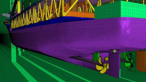
Constructing a computational mesh is one of the most important parts in conducting a CFD simulation, and always represents a compromise between accuracy and computational cost.
In practical terms, a “fine mesh” that is constructed from a large number of small computational cells provides a more accurate prediction than a “coarse mesh” of larger cells. However, a greater number of cells results in a larger computational cost, requiring more computer resources and longer simulation times compared with a coarser mesh. Since the computer resources available for a given simulation are finite and, in order to be useful, simulation results must be provided within a reasonable time-scale, CFD engineers have to choose how they spend their cells wisely, deploying smaller cells in areas of high rate of change close to the vessel and its wake, transitioning to larger cells further away.
Historically, providing a computational mesh that is fine enough to capture the hull, rudder and propeller in a single simulation has been challenging, and engineers have often been forced to consider the components in separate simulations (and accounting for their interactions using boundary conditions).
However, recent developments in automatic meshing technology (that provide a high quality grid with minimal manual interaction from the engineer), computer hardware (which provides lower cost computational resources) and licensing (which reduces the cost of running simulations across multiple processors) has made self-propulsion and maneuvering tests a practical proposition.
CHALLENGE 2: Wave and Water Physics
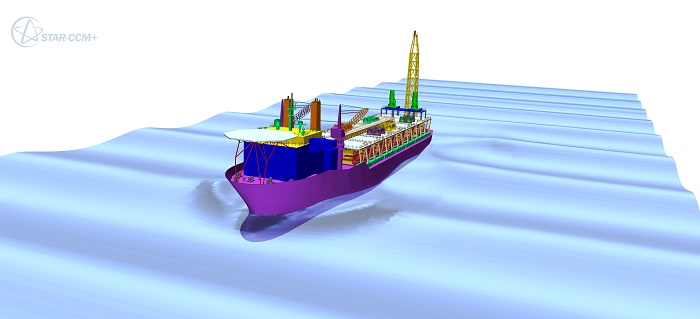
In order to accurately predict the performance of a vessel, the numerical simulation has to correctly predict for both the influence of the vessel on the surrounding sea (wake predictions) as well as the increase in resistance caused by waves.
This represents a much greater challenge than the type of “single fluid” simulations that can be used to investigate an aircraft, land-vehicle, or fully submerged vessel.
Many CFD tools deploy a “Volume of Fluid” approach that assigns a value of “1” to cells that contain water, and a value of “0” to cells that contain air. In cells marked “1” the physical properties of water are used, in the cells marked “0” the properties of air are used.
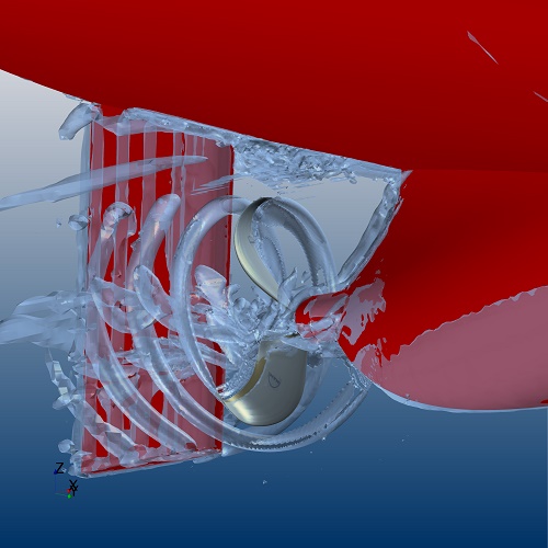
STAR-CCM+ deploys a “High Resolution Interface Capture” scheme to accurately capture the position of the free surface between water and air; this is necessary to prevent the free surface from diffusing (with cells that have a value that is somewhere between “1” and “0”). This method ensures that the interaction between the vessel and the free-surface can be accurately captured. STAR-CCM+ also provides a range of built-in higher-order wave models that can be used to test the vessel under realistic sea states.
Additionally, STAR-CCM+ also includes an extensively validated cavitation model that can be used to predict and manage the phase changes caused by the propeller.
CHALLENGE 3: Vessel Motion
Unlike the simulation of an aircraft or road-vehicle, which in ideal circumstances moves forward in a single direction, the forward progress of a ship is heavily influenced by the surrounding sea-state. Even in still water, establishing the dynamic position of the ship in relation to the sea surface (“sink and trim”) is critical to providing accurate resistance predictions. In rough seas, the full motion of the vessel in six-degrees-of-freedom must be correctly accounted for, as the vessel pitches, rolls and heaves in response to oncoming waves.
STAR-CCM+ accounts for 6DOF vessel motion in an automatic manner. The “Dynamic Fluid- Body Interaction” model integrates the forces acting on the vessel at every time step, and adjusts its position (in all-six-degrees-of-freedom) accordingly.
“Adjusts its position” means moving the computational mesh, which historically has been a difficult proposition, and various methods have been used to account for this motion. For relatively small movements, the vertices of cells in the mesh can be adjusted on a step-by-step basis. However, for large movements, this becomes impractical as individual cells become highly distorted, leading to inaccuracies in, or failure of, the simulation.
STAR-CCM+, uniquely among commercial CFD codes, solves this problem using “overset” or “chimera” meshes, in which the mesh around the vessel is independent of the mesh used to represent the sea. This allows the simulated ship to move as much as necessary. Furthermore, it can be used to model the interaction between multiple vessels or objects, such as one ship moving independently in the wake of another, or the collision of two vessels. Also, with overset mesh, the rotation of the propeller and rudder motion, in addition to propeller pitching, can all be modeled in relation to the ship motion, leading to robust, accurate self-propulsion and maneuvering analysis.
OUTLOOK
Having addressed the three main challenges to replicating the performance tests, CFD is now able to provide a useful tool to augment, if not replace, towing tank testing. Comparisons between STAR-CCM+ and tow-tank simulations have demonstrated a high degree of correlation between the two methods (typically within a few percentage points [1],[2]). Furthermore, CFD simulations also have the advantage that they can easily be deployed at full-scale if desired, reducing the uncertainty inherent in model scaling.
Although it is unlikely that any large vessel will be designed in the foreseeable future without some aid from towing tanks, CFD is now routinely being used as part of the design process by ship builders and naval architects across the world. Used effectively, CFD simulation can be used to reduce the amount and cost of physical towing tank tests by providing a more refined and optimized design that requires fewer modifications in order to meet contractual obligations.
It is also true that in certain parts of the industry, such as in the design of the high-performance vessels that compete in the America’s Cup, towing tanks have been dispensed of entirely in favor of CFD. The winning yacht in the 37th America’s Cup was designed using STAR-CCM+, as will be yachts raced by Ben Ainslie Racing and Luna Rossa in the next America’s Cup.
What of the future? Unlike towing tanks, once you have developed a robust process for simulating the performance of a vessel, it is relatively easy to automate it. This opens the door to both “automated design exploration,” where the proposed vessel is subjected to a wide range of potential operating scenarios, and “optimization,” where the design of the vessel is automatically adjusted to account for deficiencies in the performance identified in previous simulations.
Widespread adoption of this approach will not only lead to more innovative and efficient ship designs (which can be developed at lower cost), but also more robust vessels that have been numerically tested against a much wider range of real-world operating conditions than could ever be considered using a towing tank alone.

that matters most
Get the latest maritime news delivered to your inbox daily.
References
[1] http://www.cd-adapco.com/presentation/maneuvering-predictions-early-design-phase-using-cfd-generated-pmm-data
[2] http://www.dansis.dk/filarkiv/pdf-filer/2009/2/skibsdesign_force.pdf