
A Winning Formula to Reduce Emissions

[By: Cape Horn Engineering]
Climate change has become an increasingly prevalent topic in recent years. With the international shipping industry accounting for 2.89% of global emissions [1] the IMO has a considerable responsibility to regulate the sector. Efforts to reduce these emissions have accelerated rapidly, with a range of initiatives being introduced. In 2018 the Initial Strategy on the reduction of GHG was adopted, setting out a policy framework with the key ambitions of a reduction in carbon intensity of at least 40% by 2030, and a reduction in total GHG emissions of 50% by 2050, relative to 2008 levels.
The first of this framework’s short-term measures are set to come into force on January 1st, 2023, in the form of the Carbon Intensity Indicator (CII) and the Energy Efficiency Existing Ship Index (EEXI). While CII is an operational measure, assessing how efficiently a ship transports its cargo by considering the real time fuel consumption, EEXI is a technical measure that purely considers the design parameters of the vessel in a comparable way to EEDI for new builds. Despite being defined by a rather complex looking equation, EEXI is simply a measure of the design CO2 emissions relative to the vessels size and speed, producing a single value describing the emissions per cargo ton per mile. The IMO has developed limits on the allowable EEXI of a vessel based on size and type, with every ship being required to demonstrate compliance by producing an EEXI Technical File.
Using CFD Technology
CFD has an important role to play in the calculation of EEXI. Firstly, it offers a cost effective and quick solution to develop speed-power curves for older vessels whose documentation may not meet the strict requirements of the regulations. For a vessels existing model test or sea trial data to be used, it must consider the EEXI loading condition, which is not always the case. The IMO provides a statistical method which may be used in such circumstances, but this includes a conservative safety factor. Given that less than 25% of bulkers and tankers are estimated to achieve EEXI compliance [2], employing this conservative calculation for the ships reference speed will highlight the inefficiencies and move the vessels further away from compliance. The existing data may be used to validate a CFD model, which can then then be used to develop an accurate speed-power curve for the correct loading condition for use in the EEXI calculation. The second situation in which CFD excels as a powerful tool is when energy saving devices are installed and it becomes necessary to calculate the efficiency improvements so their impact on EEXI may be determined.
Tank testing is the traditional method by which speed-power curves can be obtained; however, it is expensive and time consuming by comparison to CFD. The ability to rapidly update geometries to explore a range of solutions is lost, and complex scaling issues need to be considered. Converting model scale results to full scale relies upon empirical formulas, and the different scaling laws of hydrodynamics and aerodynamics makes accurately performing coupled experiments extremely challenging when investigating WASP devices (Wind Assisted Ship Propulsion). Alternatively, employing CFD allows the vessel to be modelled in full scale, completely mitigating these issues.
While CFD is a powerful tool for calculating speed-power curves, the IMO places strict conditions upon its use. For the results to be considered by a validator they must have been developed in accordance with ITTC Verification and Validation (V&V), and Quality Control documentation. In fairness, this is good practice when using CFD and is something that all competent providers should be undertaking regularly to ensure that their methods are accurate. One of the main concerns facing the wider acceptance of CFD is trust in the results, and the solution to this is to consistently show your methods to be accurate and to quantify and understand the levels of numerical uncertainty through V&V processes.
Verification is the process of assessing a simulation’s numerical uncertainty and determines whether a CFD simulation accurately represents the developer's conceptual description of the model. It investigates whether the set-up is “Solving the equations right” and quantifies the errors arising from factors such as spatial and temporal discretisation. Validation is the process of assessing a simulation’s modelling uncertainty in relation to benchmark data and determines how closely a CFD simulation represents the real-world condition, investigating whether the set-up is “solving the right equations”. Both validation and verification are vital to ensuring that confidence may be held in the results of a simulation.
Cape Horn Engineering
As industry leaders in Computational Fluid Dynamics (CFD), Cape Horn Engineering specialise in hydrodynamic analysis, offering their consultancy services and state-of-the-art expertise in flow analysis for performance prediction and design improvement. Using their extensive experience, they offer unique solutions and insight into how this revolutionary technology can assist designers to improve performance and efficiency, leading to considerable fuel and emission reductions.
The levels of accuracy that may be expected when employing CFD to calculate an EEXI speed power curve are demonstrated by Cape Horn Engineering’s show case EEXI project. This was undertaken using the general cargo vessel, the Regal, for which detailed sea data was published as part of the Workshop on Full-Scale Ship Hydrodynamics organised by Lloyds Register. In these simulations the vessel was moving at a constant speed whilst free to sink and trim. The thrust of the propeller was balanced with the resistance of the vessel to obtain the Torque, RPM and Delivered Power. The propulsion was modelled both using the Virtual Disk method, in which the propeller is modelled as an actuator disk, and with the more computationally demanding Rotating Propeller method in which the rotating 3D geometry of the propeller is modelled.
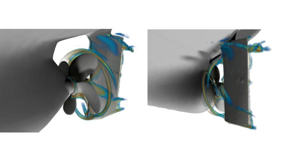
Rotating Propeller Geometry
Both configurations performed well with the virtual disk results differing from the sea trial results by 1.5% for RPM, 3.4% for torque and 1.8% for shaft power. The higher fidelity rotating propeller set-up performed even better, with 1.8% for RPM, 1.1% for torque and 2.9% for shaft power. The following V&V study showed both set-ups to be considered valid by the ITTC definitions, with uncertainties of 0.2% for RPM, 2.1% for Torque and 3.7% for Delivered Power. The level of accuracy with which CFD is able to replicate the sea trial results gives a good idea of how powerful this tool is in determining the performance of a full-scale ship.
In the likely event that a vessels EEXI limits are exceeded, the owner is required to implement measures that moderate its emissions. Often the simplest and most effective solution is to limit the main engine power and operate the vessel at a reduced service speed. At times however, this is infeasible and Energy Saving Devices (ESD) such as enhanced propellers or additional propulsion technology must be investigated. This is the second situation in which CFD is a powerful tool, capable of calculating a new speed-power curve that fully accounts for the effects of the ESD and quantifying the reduction in emissions. Given that a well set up CFD process allows for rapid, or even automated geometry modifications, it provides the perfect environment in which to test several solutions, or even undertake full optimisation studies to ensure that the full potential of the ESD is realised and that the maximum emissions reduction is achieved.
One of the most promising technologies that is receiving a lot of attention is Wind Assisted Ship Propulsion (WASP) devices such as wing sails, suction sails, Flettner rotors, or any other wind powered devices. These systems have been seen to offer fuel savings in the 10 to 30% range when retrofitted to existing vessels [3].
Cape Horn Engineering has developed a simulation workflow to directly compare the efficiency of WASP devices and to determine the potential power saving. These are highly complex simulations that model both the hydrodynamic and aerodynamic effects simultaneously in a single simulation. To further increase the accuracy, the wind conditions above the water surface are modelled with a realistic wind profile considering the atmospheric boundary layer wind gradient.
These simulations are as realistic as possible, with 6 degrees-of-freedom being considered. The vessel is sailing at constant speed, with either an actuator disk or a rotating region containing the propeller geometry modelling the propulsion. This calculates the propeller torque and RPM, and thus the delivered power. The simulation further considers the waves generated by the vessel, the dynamic sinkage and trim, the drift or leeway angle, the heel angle, and the rudder angle to keep a constant course.
Both the apparent wind resulting from the vessel’s motion and the input wind conditions result in aerodynamic forces acting upon the WASP devices and the hull topsides and superstructure. These forces induce drift and heel angles. To balance the yaw moment of the whole system and ensure that the vessel’s course does not deviate, the rudder angle is altered during the simulation with the application of a PID controller.
The vessel speed is fixed, while the propeller responds to the drag of the hull and thrust from the WASP devices. The thrust produced by the propeller balances the degree-of-freedom in direction of travel. When the simulation converges to a quasi-steady solution, different WASP configurations can be directly compared by looking at the delivered power of the propeller. This offers a direct measure by which the fuel (and emissions) saving potential can be assessed.
To demonstrate this workflow two WASP configurations were fitted to the general cargo vessel, the Regal. This vessel was once again selected as the benchmark data is readily available for the all-important V&V work. The first configuration consisted of two solid wing assemblies mounted on the deck which are similar to WindShip Technology's patented 3-wing-3-flaps design. For the second configuration the wing sails were replaced by a pair of Flettner rotors of approximately the same size.
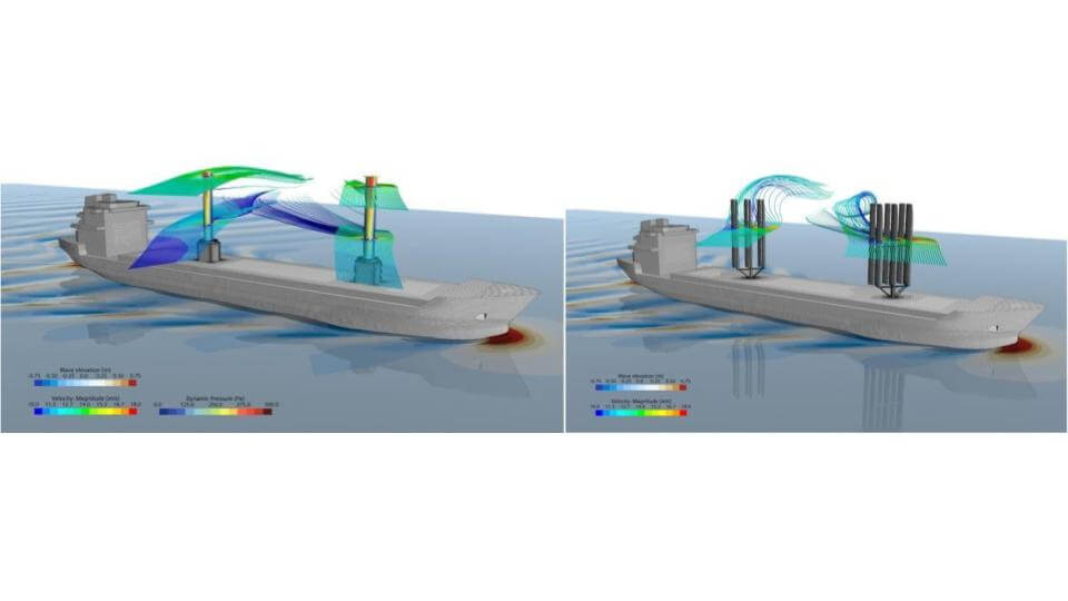
The Regal in both WASP Configurations
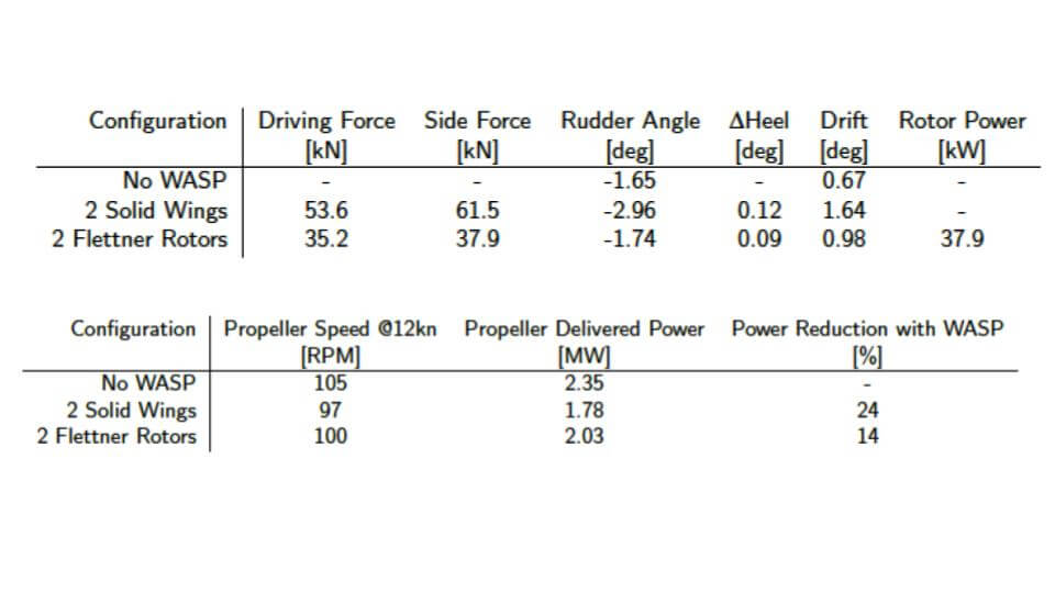
It should be noted that no attempt was been made in trimming the angles of the wing's main assemblies and flaps for best performance and the trim angle was chosen such as the flow was attached, and a reasonable amount of thrust was produced. Likewise, the rotor operating speed was taken as a nominal value with no optimization study performed. The case study did not aim to give a quantitative comparison and show the merits of one type of device over the other, but rather demonstrate the capabilities of the developed simulation set-up to compare different types of WASP devices with a highly accurate all-in-one 6-DOF hydrodynamic and aerodynamic simulation.
From the representative results it was shown that even for these unoptimized configurations there was a 14 & 25% power reduction due to the inclusion of the WASP devices. The potential of this tool is seen clearly, allowing owners to make informed decisions about what the best course of action is when considering a range of ESD solutions.
Building upon knowledge and developing cutting edge methodologies is something that those working at Cape Horn Engineering have always prided themselves in, and being at the forefront of modelling wing sails is no different. The company has recently turned its eyes to the future, working in collaboration with multiple companies and Universities to advance the use of Artificial Intelligence techniques to help reduce the emissions of ships. While modelling wing sails with CFD produces accurate results, running these simulations is computationally demanding, requiring the use of a powerful commercial supercomputer. This problem is highly exacerbated when the objective of analysis turns to optimisation, for which hundreds or even thousands of simulations would be run to fully explore the design space in an ideal world. This of course, is infeasible in most cases.
Training AI models with data sets created using CFD presents a solution to this and is something that Cape Horn Engineering has seen initial success with. We have trialled the use of Reduced Order Modelling and Neural Networks, with both producing models capable of calculating the aerodynamic forces in seconds rather than hours. This opens vast possibilities in optimising the design of wing sails, and in developing intelligent control systems to ensure that the wings are optimally trimmed when in service to ensure the largest reduction in emissions.
As environmental concerns are influencing a greater need for sustainable energy across the world, specialist technologies are at the forefront of new designs and solutions. CFD technology has become a crucial support for naval architects and design engineers to optimise designs for critical elements such as performance predictions, resistance optimisation and emissions reduction.
Cape Horn Engineering are renowned for providing best in class services to many international clients around the world. They use the most comprehensive and best CFD packages on the market, STAR-CCM+ from Siemens PLM. They are proud to be involved in innovative projects to help reduce emissions for the shipping industry.
The products and services herein described in this press release are not endorsed by The Maritime Executive.